A colleague came to me with a shower head holder and asked for help. It’s ancient, it broke, someone had glued it back together, and nobody sells a replacement any more. I promised to try. You probably know a part like that too.
I’m bad at CAD. So I gave the holder to Claude, and Claude did the rest: it told me how to photograph it, modelled it in Fusion 360, wrote the 3MF and sliced it for my Bambu Lab H2C.
Earlier Claude models didn’t do a good job at this. This time it impressed me. A lot. I’ve argued that every household should have a 3D printer.
Replacement part from photos: what Claude did, start to finish
Claude covered every step between a worn part and a print job, and I handled two of them: the camera and the caliper.
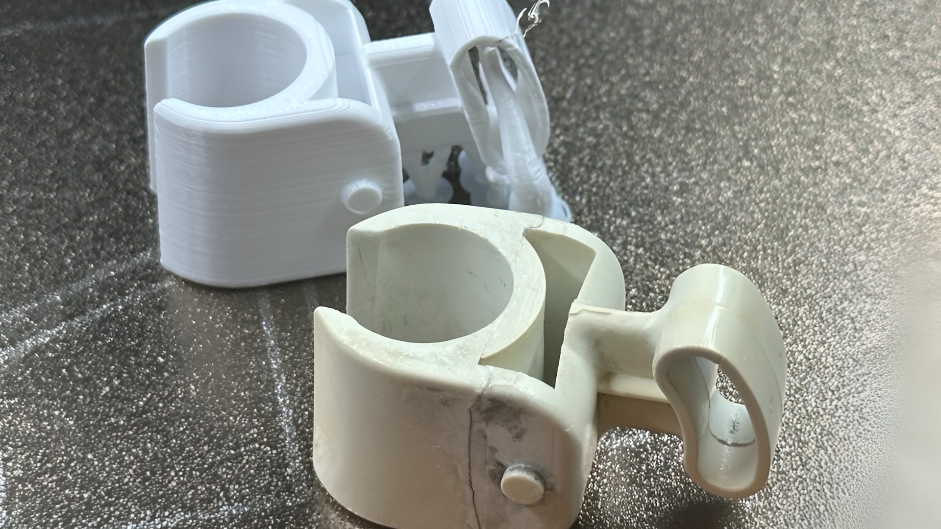
It asked for photos with a ruler in frame. It turned them into a 3D model, then made the print file and chose the printer settings. 50 minutes of white PETG later I had a new holder next to the original.
It didn’t work the first time. On 3 November Claude built a first model from my measurements. I looked at the result and told it the ring at the back “doesn’t match at all”. It had drawn a straight oval where the original curves like a kidney. The day ended with me writing that we had burned all the tokens and not made it.
The second attempt, five days later, traced the photos and was corrected by three measurements. The rest of this post is how.
Photographing a part for Claude: the rules it gave me
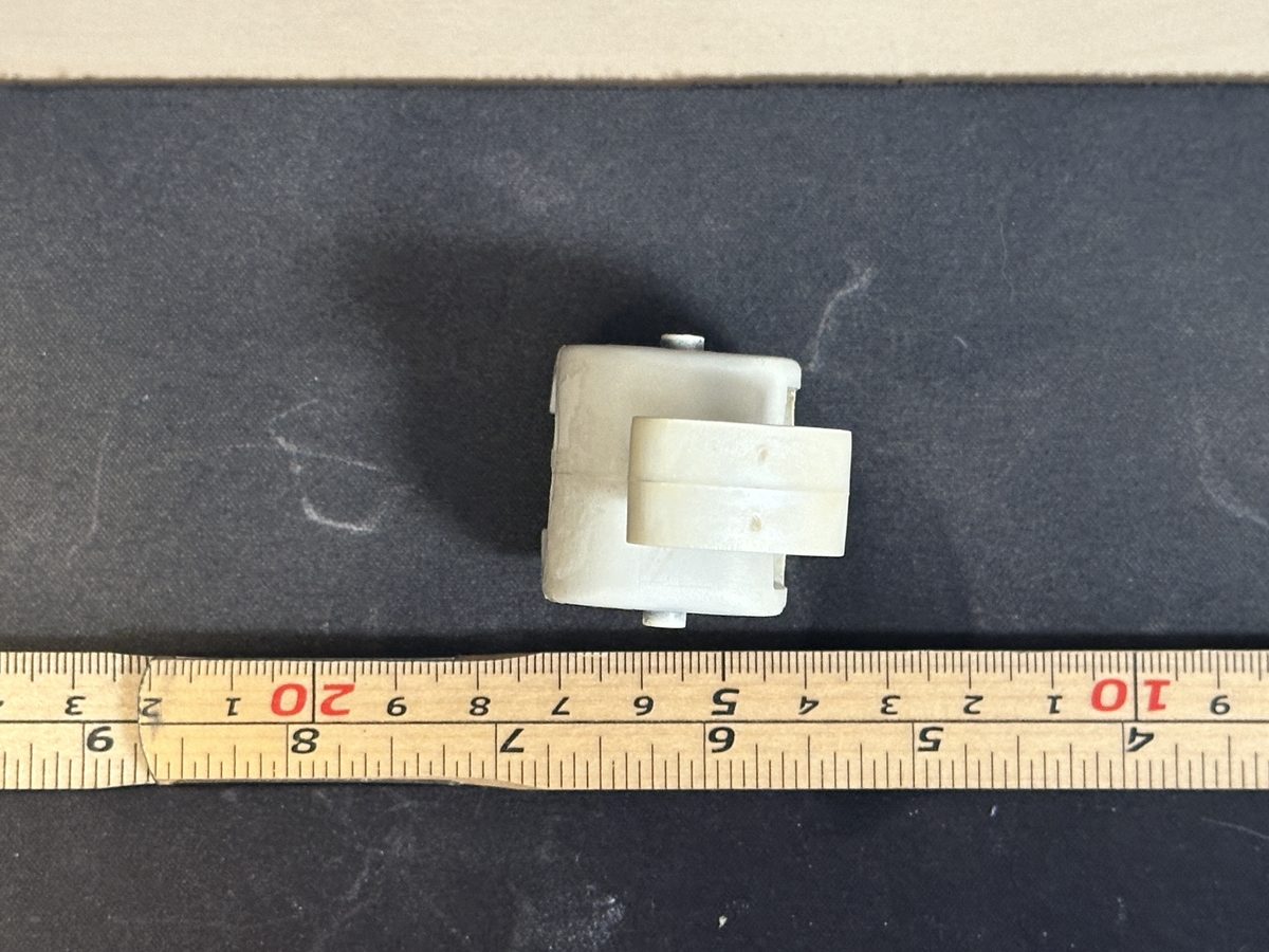
Claude asked for a straight-on photo with the ruler in the same plane as the surface it had to trace. On the first attempt the ruler lay on the table next to a part that stands 28 mm tall, and measured against it the photo made the part about 10 percent too big.
On 8 November I asked what lens to use. I have a 90 mm macro, a 70-200 and a tripod, and the part is about 55 mm long. Claude’s advice:
- 90 mm macro at the minimum focus distance, about 30 cm.
- f/8 to f/11 and ISO 100. Depth of field is only about 5 mm even at f/11.
- Tripod and a two-second self-timer.
- Calibrate on two marks far apart on the ruler, not on one.
- Check which scale you read. The lower scale on mine is inches, a 2.54 times error waiting to happen.
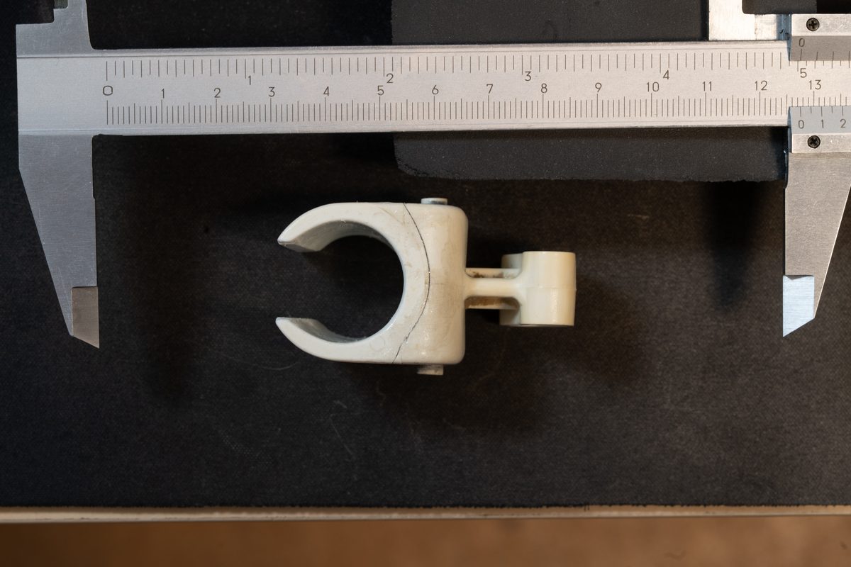
I shot the final photos with the 90 mm at 30 cm, f/11 and ISO 640.
My first Sony shots were taken at an angle with the ruler at the top of the frame. Claude read the side view at 6.5 cm against 5.5 cm on the caliper and told me to reshoot. The phone photos from the first attempt were off by 5 to 7 percent, by Claude’s own visual reading of the ruler.
Fusion 360 from photos: trace the image, don’t build from numbers
Claude drives Fusion 360 through a local MCP server that runs Python scripts, and it works when you tell it to trace the photo and not to build from the numbers.
The first attempt built the geometry from my caliper values and used the photos only as a check. Claude wrote the correction into its own project instructions, and here it is, ready to paste into yours:
Put each reference photo in Fusion as a canvas on its own plane, outside the part, and sketch on that same plane.
Trace the contour in the photo with lines and arcs. Add the caliper dimensions afterwards.
Never build the geometry from the parameters and use the photo only as a check.
Calipers decide the size, the photo decides the shape. Expect about 5 percent perspective error.
Calibrate scale from the millimetre ticks, but take rotation from the part itself.
Ask for 2 to 3 control measurements drawn on the photos, one per image axis. Scale the model with one factor per axis.
On the second attempt Claude found about 125 millimetre ticks on the caliper with numpy and got 50.82 pixels per millimetre on the top and underside photos. It placed three canvases on three planes, with the pin centre as origin, and traced the outline from each. It also named the weak spot: the surfaces it traced sat 14 to 28 mm above the caliper scale, so it expected the model to be 3 to 5 percent too big.
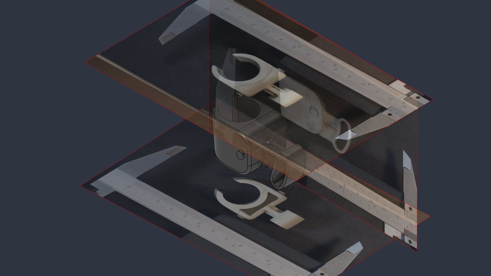
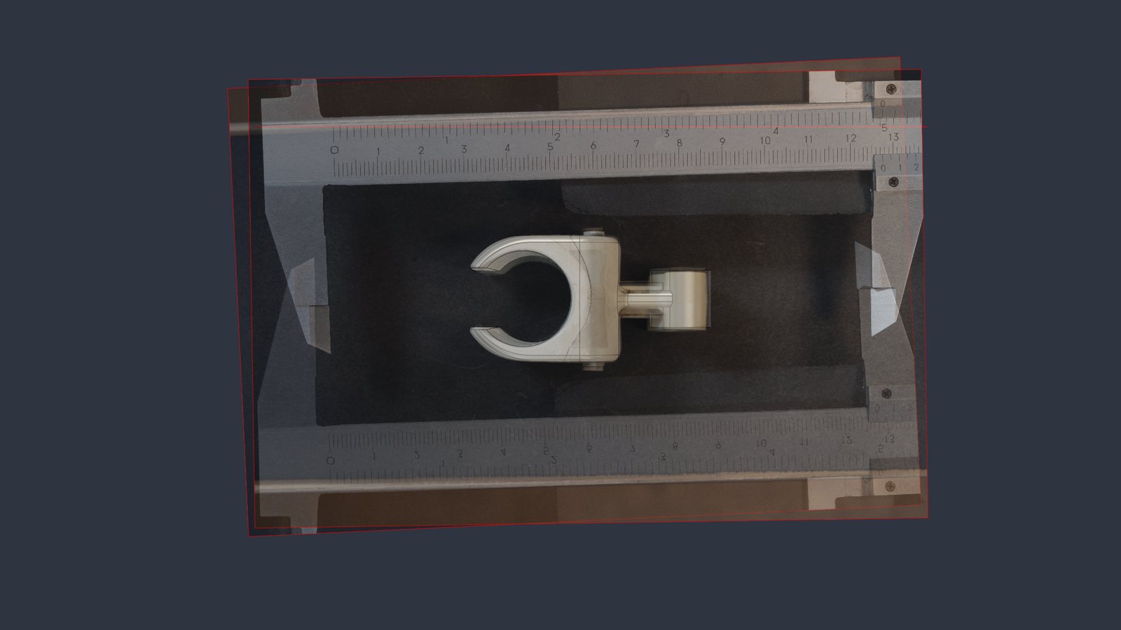
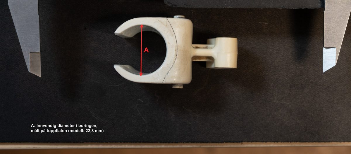
That is why the control measurements matter. I measured three things on the real part and Claude marked them on the photos:
| Measure | Claude’s model | Real part |
|---|---|---|
| A: bore at the top face | 22.8 mm | 22.4 mm |
| B: bore at the underside | 20.2 mm | 20.0 mm |
| C: total height | 27.2 mm | 28.0 mm |
The top photos were 1.4 percent too large and the side photo 2.9 percent too small. Claude applied 0.986 in X and Y and 1.029 in Z, rebuilt, and the model came out at 22.40, 20.00 and 27.99 mm. This is the step I’d copy for any object you photograph.
3MF and Bambu Studio from the command line
Claude exported one body as klemme.3mf and sliced it by running bambu-studio.exe itself, because my H2C exists as a profile in Bambu Studio and not in Orca Slicer.
I asked whether it had run Bambu Studio headless. It had. It merged the inheritance chains of the system profiles under %APPDATA%\BambuStudio\system\BBL into flat JSON files and ran this:
bambu-studio.exe --slice 0 --load-settings "machine.json;process.json" --load-filaments filament.json --outputdir out --export-3mf
The executable prints nothing to the console, so Claude read result.json instead. The first run came back with error -61, “Filaments are not compatible with the plate type”. The process profile needed curr_bed_type set to Textured PEI Plate. The second run returned 0.
The settings Claude picked: top face down, Bambu PETG Basic in white, 0.20 mm layers, 5 walls, 5 top and 5 bottom layers, 40 percent gyroid, tree supports from the plate only. The estimate was 50 minutes and 15.5 g of filament. Claude opened the sliced file in Bambu Studio, and I sent it to the printer.
First print, second print, and the fit
The first print looked almost perfect, but I suspected it was slightly off. I asked Claude to check as carefully as it could, and it found three things. Two mattered: the arms were short and the stem met the block with a sharp corner. The third, a squarer stem, was cosmetic.
I measured two more distances on the original. The arm length D was 34.5 mm at the top and 33.5 mm at the bottom. The model had 33.4 and 30.9 mm, so the arms were 1.1 and 2.6 mm short. The model ended the tips on the outer circle, which cut them short. The opening between the tips, E, was correct.
Claude redrew the tips with tangent arcs and changed the fillet where the stem meets the block from R0.6 to R2.5. Two Fusion API traps made it into Claude’s own notes while it rebuilt: setting ExtrudeFeature.profile again resets isFullLength on a symmetric extent, so you set it back afterwards, and sketches and features need different names, or Fusion adds a “(1)” suffix to the feature. For the second print Claude exported the body to klemme.3mf and turned it top face down by flipping the mesh 180 degrees about X in the 3MF’s XML (klemme_print.3mf). It then ran the same slicer command as before. Claude’s second slice came to 50 minutes and 16.1 g. I turned on variable layer height in Bambu Studio, which made it 54 minutes.
The second clip fit. I took the broken original home, so I could hold the two side by side. My colleague gets the new one on Tuesday, and that is the real test. I’m excited.
The takeaway
Photograph the part straight on, with the ruler in the same plane, and measure three things on the real part. Claude does the rest.
FAQ
Can Claude really drive Fusion 360?
Yes, through a local MCP server for Fusion that runs Python scripts. In my sessions it set canvases, drew sketches, made features and exported the 3MF.
Which printer and slicer did you use?
A Bambu Lab H2C, with Bambu Studio and Bambu PETG Basic in white on a Textured PEI plate. Orca Slicer has no H2C profile, so the command-line slicing went through Bambu Studio.
How accurate was the first model?
Close enough to look right and wrong enough to fail a caliper. The arms were 1.1 and 2.6 mm short, and the height was off by 0.8 mm before the control measurements.
Do I need a macro lens?
I used one because the part is 55 mm long. The rules that mattered were not about the lens: shoot straight on, keep the ruler in the surface plane and measure control values on the real part.